


 700 / 816

SECTION 21 -
SPENCER FRANKLIN HYDRACLAMP, HYDRAULICS
AND PNEUMATICS
WDS
WDS
www.wdsltd.co.uk21-31
&
0845 606 66 77
•
:
www.wdsltd.co.uk•
*
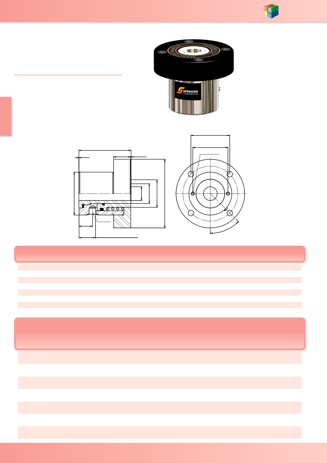
sales@wdsltd.co.ukFlange Mounted Hollow Cylinders
Single Acting and Single Acting
Spring Return
SF-3402F-3408F
R HOLES ON
S P.C.D.
M
N x 8 DEEP
REFER
TO CHART
A
P 0.76
J
F
G
B
H
0.25
E
L BLEED SCREW
D INLET
3406F
Dimensions in mm
Stroke
with
spring
Stroke
without
spring
Effective
Area cm²
Swept
Volume
with
Spring
cm³
Swept
Volume
without
Spring
cm³
Weight
with
Spring
kg
Weight
without
Spring kg
Bleed
Screw
Position
WDS No.
P
R
S
25.4
8.7 DIA THRO' C/BORED
14.3 DIA x 8.4 DEEP
77.8 15.75 31.24 12.7 20.5 40 1.5 1.45
180°
SF-3402F
25.4
8.7 DIA THRO' C/BORED
14.3 DIA x 8.4 DEEP
77.8 7.87 18.03 12.7 10.5 22.9 0.91 0.86
45°
SF-3403F
35.54
8.7 DIA THRO' C/BORED
14.3 DIA x 8.4 DEEP
77.8 38.1 63.5 12.7 48.7 81.1 2.61 2.5
180°
SF-3404F
25.4
8.7 DIA THRO' C/BORED
14.3 DIA x 8.4 DEEP
77.8 39.4 82.5 12.7 50.3 105 3.91 3.75
180°
SF-3405F
31.75
10.3 DIA THRO' C/BORED
16.6 DIA x 10.5 DEEP
101.6 17.02 31.75 21.2 33.4 67.3 3.18 3.13
180°
SF-3406F
34.92
13.5 DIA THRO' C/BORED
20.6 DIA x 13.2 DEEP
114.3 13.46 29.97 31.4 42.3 94.4 3.86 3.74
180°
SF-3407F
40
18 DIA THRO' C/BORED
26 DIA x 16 DEEP
130 19 60 34.3 54.9 206 8.65 8.48
N/A SF-3408F
TECHNICAL INFORMATION
-
Max Operating Pressure =
275 BAR (4000 P.S.I)
T
heoretical Thrust (N) =
Oil Pressure (bar) x Effective Area (cm²)
External stop must be used with spring return version
A
B
C
D
B.S.P.
E
F
G
H
J
K
L
M N
WDS No.
82.55 63.5 0.76 ¼"
22 17.45 25.4 38.1 95.2 0.25 24.4 50 M6x1.0 SF-3402F
55.55 63.5 0.76 ¼"
22 17.45 25.4 38.1 95.2 0.25 15 50 M6x1.0 SF-3403F
127.7 63.5 0.76 ¼"
22 17.45 25.4 38.1 95.2 0.25 22 50 M6x1.0 SF-3404F
127.7 63.5 0.76 ¼"
11 17.45 25.4 38.1 95.2 0.25 15.8 44.5 M6x1.0 SF-3405F
97.76 79.38 0.76 ¼"
25 25.78 36.5 50.8 127 0.25 30.5 65 M6x1.0 SF-3406F
96.19 88.9 0.76 ¼"
25 25.78 36.5 60.3 139 0.25 30.5 65 M6x1.0 SF-3407F
143 100 -
3
⁄
8"
24 31 45 60 160 -
-
70 M6x1.0 SF-3408F
Re
fer to page 21-46 & 21-47 for
more technical information