


 694 / 816

SECTION 21 -
SPENCER FRANKLIN HYDRACLAMP, HYDRAULICS
AND PNEUMATICS
WDS
WDS
www.wdsltd.co.uk21-25
&
0845 606 66 77
•
:
www.wdsltd.co.uk•
*
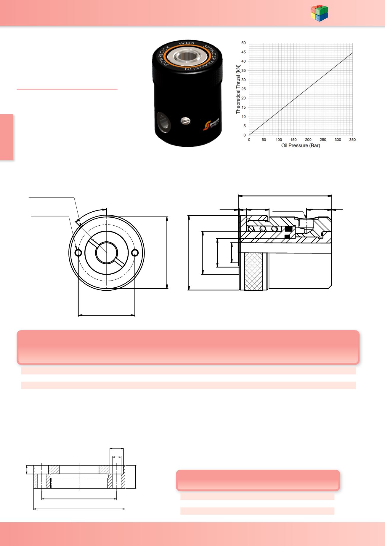
sales@wdsltd.co.ukPowRlock OpenRam Head
SF-3100MF -
3300MF
50 P.C.D.
E
45°
M6 x 8 DEEP
BLEED SCREW
K
J
F
1/4" B.S.P.
A
B
C
D
G
H
3200MF
* Do not exceed Maximum Stroke
All ports are ¼" BSP
Mounting: To include these heads in a fixture it is only necessary to retain them over 16mm dia. studs or bolts via the hole through the centre
of each head.
OPTIONAL VARIATIONS FOR STANDARD TYPE 3520 POWRAM
Part No SF-3100FL/SF-3200FL/SF-3300FL - Front flange mounting (circular)instead
of screwed cap.
Dimensions in mm
Flange No.
A B C D E F
95.2 77.8 8.4 25.4 14.3 8.7 SF-3101FL
95.2 77.8 8.4 25.4 14.3 8.7 SF-3201FL
95.2 77.8 8.4 35.6 14.3 8.7 SF-3301FL
Note: Unless otherwise stated assume there are four counter
bored holes equi-spaced on ØB.
Stroke*
Effective
Area cm²
Swept Volume
Dimensions in mm
Weight
WDS No.
Seal Kit
No.
With
Spring
mm
Without
Spring
mm
With
Spring
cm³
Without
Spring
cm³
A B C D E F G H J K
With
Spring
kg
Without
Spring
kg
7.9 18.0
12.8 10.5 22.9 17.5 25.4 38.1 66.7 63.5 11.1 55.6 0.3 0.8 19.8 0.9 0.9 SF-3100MF SF-3199
15.8 31.2
12.8 20.5 40.0 17.5 25.4 38.1 66.7 63.5 22.2 82.6 0.3 0.8 19.8 1.5 1.5 SF-3200MF SF-3199
38.1 63.5
12.8 48.7 81.1 17.5 25.4 38.1 66.7 63.5 19.1 128 0.3 0.8 17.5 2.6 2.5 SF-3300MF SF-3199
C
C
A
D
F
E
C
B
GE FOR:
-3525
B
MF-3300MF
A
A
NOTE: All graphs are Rams with Springs fitted.
Graphs are calculated using theoretical pressures and
actual values will be less due to loss in system pressure.
TECHNICAL INFORMATION
-
Max Operating Pressure =
350 BAR (5000 P.S.I)
T
heoretical Thrust (N) =
Oil Pressure (bar) x Effective Area (cm²)
Re
fer to page 21-46 & 21-47 for
more technical information