


 255 / 816

SECTION 5 - HAND KNOBS
WDS
&
0845 606 66 77
•
:
www.wdsltd.co.uk•
*
sales@wdsltd.co.uk5-16
WDS
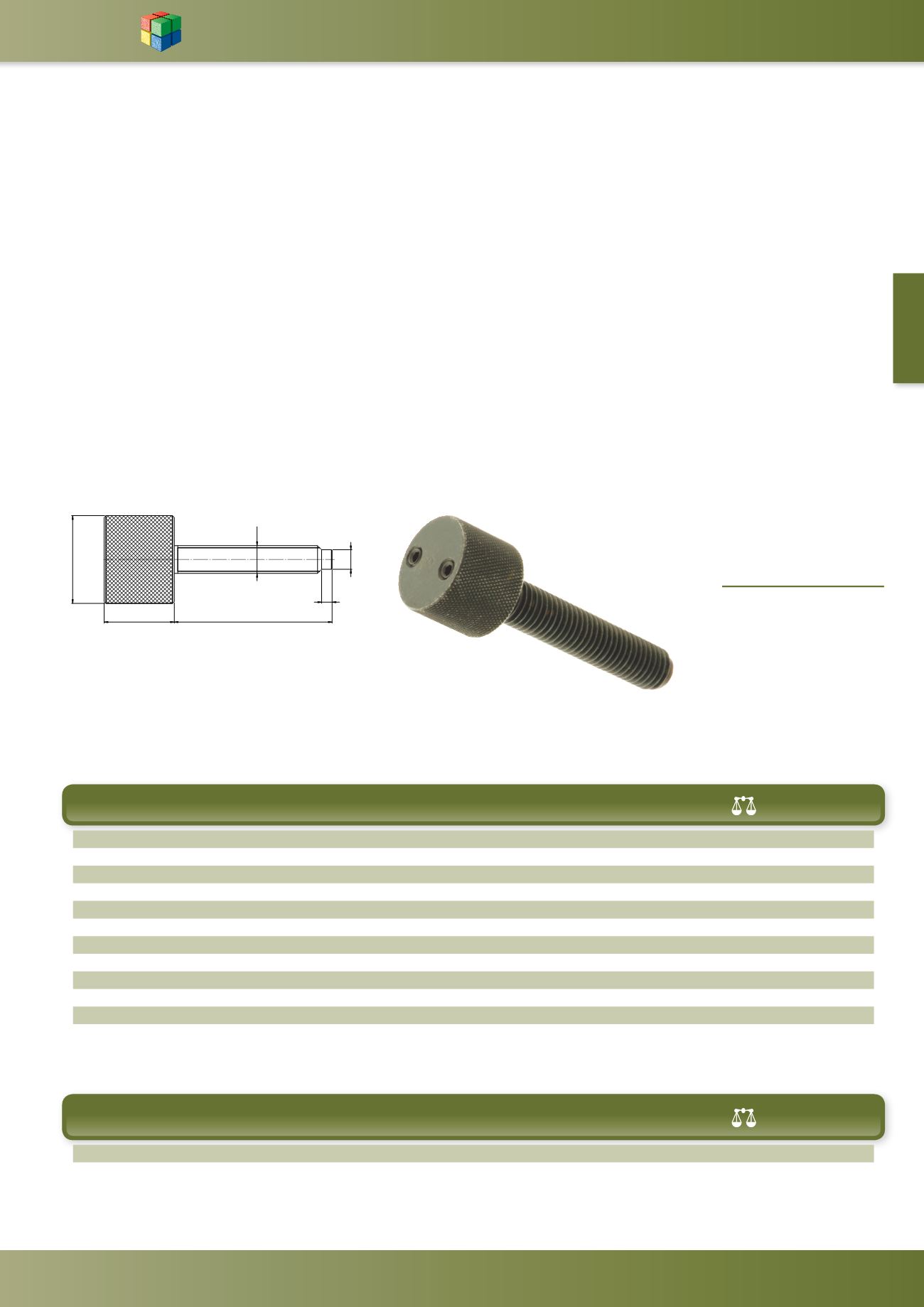
www.wdsltd.co.ukTorque Screw
WDS 700
MATERIAL
-
Head - Steel
BS.970 Gr.220M07
Screw - Steel
BS.970 Gr.212A42
Chemical Black Finish
Torque Screws and Knobs Section
Torque applied to the knurled knob is transmitted to the driving plate of the screw by means of two spring loaded
balls in conical seatings, thereby tightening the screw. Dependent upon the spring loading, the balls will be forced up
the inclined sides of the dimples until they reach the flat surface of the driving plate. Slippage will then occur and no
further increase in the clamping load of the screw is possible. To unclamp, the screw is turned in an anti clockwise
direction.
Should the clamping load be too great, then this can be reduced by adjusting the spring pressure on the balls.
Slackening of the grub screws will reduce the load exerted by the springs. To increase the clamping load of the screw,
the grub screws should be tightened. Care should be taken not to screw them too far otherwise the balls will become
locked solid in the seatings and the torque action become non-operative. Adjustments should only be carried out
whilst the screw is in a non-working situation. The whole assembly is retained by means of a circlip.
Once the required clamping load by the screw has been achieved, it will be repeated to a reasonable tolerance on
successive components.
F1 = Minimum end pressure (kg)
F2 = Maximum end pressure (kg)
D
L
D1
D2
H
E
F1
F2
(g)
WDS No.
M6
40
25
4.5
20
3
4
80
75
700-201
M6
60
25
4.5
20
3
4
80
77
700-202
M8
40
25
6.0
20
3
4
65
80
700-203
M8
60
25
6.0
20
3
4
65
85
700-204
M8
80
25
6.0
20
3
4
65
90
700-205
M10
40
25
7.8
20
3
4
55
95
700-206
M10
60
25
7.8
20
3
4
55
105
700-207
M10
80
25
7.8
20
3
4
55
110
700-208
M12
40
25
9.4
20
3
4
45
100
700-209
M12
60
25
9.4
20
3
4
45
115
700-210
M12
80
25
9.4
20
3
4
45
125
700-211
M12
100
25
9.4
20
3
4
45
140
700-212
Metric
D
L
D1
D2
H
E
F1
F2
(g)
WDS No.
UNC
1
⁄
4
45
25
4.4
20
3
4
80
80
700-45
5
⁄
16
45
25
5.6
20
3
4
60
85
700-47
Inch
'
'
(
/
+
'
) 0LQLPXP HQG SUHVVXUH NJ
) 0D[LPXP HQG SUHVVXUH NJ